


The general syntax for including a lossy (W Element) transmission line element in a Star-Hspice netlist is:
RLGC file form:
Wxxx in1 <in2 <...inx>> refin out1 <out2 <...outx>> refout
+ <RLGCfile = fname> N = val L = val
U-model form:
Wxxx in1 <in2 <...inx>> refin out1 <out2 <...outx>> refout
+ <Umodel = mname> N = val L = val
Field Solver form:
Wxxx in1 <in2 <...inx>> refin out1 <out2 <...outx>> refout
+ <FSmodel = mname> N = val L = val
where the number of ports on a single transmission line are not limited. One input and output port, the ground references, a model or file reference, a number of conductors and a length are all required.
|
Lossy (W Element) transmission line element name. Must begin with a "W", which can be followed by up to 1023 alphanumeric characters. |
|
|
Signal input node for the xth transmission line (in1 is required). |
|
|
Signal output node for the xth transmission line (each input port must have a corresponding output port). |
|
|
File name reference for file containing the RLGC information for the transmission lines (see W Element Transmission Line Properties Inputs for syntax). |
|
|
Physical length of the transmission line in units of meters. |
|
|
U-model lossy transmission-line model reference name. A lossy transmission line model, used here to represent the characteristics of the W-element transmission line. |
|
|
Internal field solver model name. References the PETL internal field solver as the source of the transmission-line characteristics (see W Element Transmission Line Properties Inputs for syntax). |
Lossy transmission line W1 connected from node in to node out with both signal references grounded, using the RLGC file named cable.rlgc and length of 5 meters.
W1 in gnd out gnd RLGCfile = cable.rlgc N = 1 L = 5
Two-conductor lossy transmission line Wcable is connected from nodes in1 and in2 to out1 and out2 with grounds on both signal references. References the
U-model named umod_1 and is 10 meters in length.
Wcable in1 in2 gnd out1 out2 gnd Umodel = umod_1 N = 2 L = 10
Five-conductor lossy transmission line Wnet1 connected from nodes i1, i2, i3, i4 and i5 to nodes o1, o3, o5 and the second and fourth outputs grounded with both signal references grounded as well. References the Field Solver model named board1 and is 1 millimeter long.
Wnet1 i1 i2 i3 i4 i5 gnd o1 gnd o3 gnd o5 gnd FSmodel = board1
+ N = 5 L = 1m
The order of parameters in the W-element card does not matter and the number of signal conductors, N, can be specified after the list of nodes. Moreover, the nodes and parameters in the W-element card can be mixed freely.
Only one of the RLGCfile,FSmodel or Umodel models can be specified in a single W-element card.
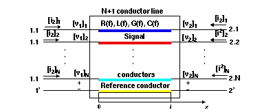
Terminal Node Numbering for W Element shows the node numbering convention for the element syntax.
The general syntax for including a lossless (T Element) transmission line element in a Star-Hspice netlist is:
General form:
Txxx in refin out refout Z0 = val TD = val <L = val> <IC = v1,i1,v2,i2>
or
Txxx in refin out refout Z0 = val F = val <NL = val> <IC = v1,i1,v2,i2>
U-model form:
Txxx in refin out refout mname L = val
where only one input and output port is allowed.
Transmission line T1 connected from node in to node out with both signal references grounded, with a 50 ohm impedance and a 5 nanosecond per meter transmission delay and a length of 5 meters.
T1 in gnd out gnd Z0 = 50 TD = 5n L = 5
Transmission line Tcable is connected from node in1 to out1 with grounds on both signal references, a 100 ohm impedance, and a normalized electrical length of 1 wavelength at 100 kHz.
Tcable in1 gnd out1 gnd Z0 = 100 F = 100k NL = 1
Transmission line Tnet1 connected from node driver to node output with both signal references grounded. References the U-model named Umodel1 and is 1 millimeter long.
Tnet1 driver gnd output gnd Umodel1 L = 1m
The general syntax for including a lossy (U Element) transmission line element in a Star-Hspice netlist is:
General form:
Uxxx in1 <in2 <...in5>> refin out1 <out2 <...out5>> refout mname
+ L = val <LUMPS = val>
where the number of ports on a single transmission line are limited to five in and five out. One input and output port, the ground references, a model reference and a length are all required.
Lossy transmission line U1 connected from node in to node out with both signal references grounded, using the U-model named umodel_RG58 and length of 5 meters.
U1 in gnd out gnd umodel_RG58 L = 5
Two-conductor lossy transmission line Ucable is connected from nodes in1 and in2 to out1 and out2 with grounds on both signal references. References the
U-model named twistpr and is 10 meters in length.
Ucable in1 in2 gnd out1 out2 gnd twistpr L = 10
Five-conductor lossy transmission line Unet1 connected from nodes i1, i2, i3, i4 and i5 to nodes o1, o3, o5 and the second and fourth outputs grounded with both signal references grounded as well. References the U-model named Umodel1 and is 1 millimeter long.
Unet1 i1 i2 i3 i4 i5 gnd o1 gnd o3 gnd o5 gnd Umodel1 L = 1mStar-Hspice Manual - Release 2001.2 - June 2001