LEVEL 3 IDS: Empirical Model
This sections provides the LEVEL 3 IDS: Empirical model parameters and equations.
LEVEL 3 Model Parameters
The LEVEL 3 model parameters follow.
Basic Model Parameters
|
Name (Alias)
|
Units
|
Default
|
Description
|
|
LEVEL
|
|
1.0
|
DC model selector. LEVEL=3 is an empirical model.
|
|
COX
|
F/m
2
|
3.453e-4
|
Oxide capacitance per unit gate area. If this parameter is not specified, it is calculated from TOX.
|
|
DERIV
|
|
1
|
Derivative method selector
DERIV=0: analytic
DERIV=1: finite difference
|
|
KAPPA
|
V
-1
|
0.2
|
Saturation field factor. This parameter is used in the channel length modulation equation.
|
|
KP (BET, BETA)
|
A/V
2
|
2.0e-5
|
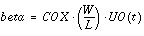
Intrinsic transconductance parameter. If this parameter is not specified and UO and TOX are entered, KP is calculated from
KP = UO
·
COX
|
|
TOX
|
m
|
1e-7
|
Gate oxide thickness
|
|
VMAX (VMX)
|
m/s
|
0.0
|
Maximum drift velocity of carriers. Use zero to indicate an infinite value.
|
Effective Width and Length Parameters
|
Name (Alias)
|
Units
|
Default
|
Description
|
|
DEL
|
m
|
0.0
|
Channel length reduction on each side
DELscaled = DEL
·
SCALM
|
|
LD (DLAT, (LATD)
|
m
|
|
Lateral diffusion into channel from source and drain diffusion,
If LD and XJ are unspecified, LD Default= 0.0.
If LD is unspecified but XJ is specified, LD is calculated from XJ as LD = 0.75
·
XJ.
|
|
LDAC
|
m
|
|
This parameter is the same as LD, but if LDAC is included in the .MODEL statement, it replaces LD in the Leff calculation for AC gate capacitance.
|
|
LREF
|
m
|
0.0
|
Channel length reference
LREFscaled = LREF
·
SCALM
|
|
LMLT
|
|
1.0
|
Length shrink factor
|
|
WD
|
m
|
0.0
|
Lateral diffusion into channel width from bulk
WDscaled = WD
·
SCALM
|
|
WDAC
|
m
|
|
This parameter is the same as WD, but if WDAC is included in the .MODEL statement, it replaces WD in the Weff calculation for AC gate capacitance.
|
|
WMLT
|
|
1.0
|
Diffusion layer and width shrink factor
|
|
WREF
|
m
|
0.0
|
Channel width reference
WREFscaled = WREF
·
SCALM
|
|
XJ
|
m
|
0.0
|
Metallurgical junction depth
XJscaled = XJ
·
SCALM
|
|
XL (DL, LDEL)
|
m
|
0.0
|
Length bias accounts for masking and etching effects
XLscaled = XL
·
SCALM
|
|
XW (DW, WDEL)
|
m
|
0.0
|
Width bias accounts for masking and etching effects
XWscaled = XW
·
SCALM
|
Threshold Voltage Parameters
|
Name (Alias)
|
Units
|
Default
|
Description
|
|
DELTA
|
|
0.0
|
Narrow width factor for adjusting threshold
|
|
ETA
|
|
0.0
|
Static feedback factor for adjusting threshold
|
|
GAMMA
|
V
1/2
|
0.5276
|
Body effect factor. This parameter is calculated from NSUB if not specified (See Common Threshold Voltage Parameters).
|
|
LND
|
µm/V
|
0.0
|
ND length sensitivity
|
|
LN0
|
µm
|
0.0
|
N0 length sensitivity
|
|
ND
|
V
-1
|
0.0
|
Drain subthreshold factor
|
|
N0
|
|
0.0
|
Gate subthreshold factor (typical value=1)
|
|
NFS (DFS,NF, DNF)
|
cm
-2
·
V
-1
|
0.0
|
Fast surface state density
|
|
NSUB (DNB, NB)
|
cm
-3
|
1e15
|
Bulk surface doping. This parameter is calculated from GAMMA if not specified.
|
|
PHI
|
V
|
0.576
|
Surface inversion potential. This parameter is calculated from NSUB if not specified (see Common Threshold Voltage Parameters).
|
|
VTO (VT)
|
V
|
|
Zero-bias threshold voltage. This parameter is calculated if not specified (see Common Threshold Voltage Parameters).
|
|
WIC
|
|
0.0
|
Sub-threshold model selector
|
|
WND
|
µm/V
|
0.0
|
ND width sensitivity
|
|
WN0
|
µm
|
0.0
|
N0 width sensitivity
|
Mobility Parameters
|
Name (Alias)
|
Units
|
Default
|
Description
|
|
THETA
|
V
-1
|
0.0
|
Mobility degradation factor
|
|
UO (UB,UBO)
|
cm
2
/
(V
·
s)
|
600(N) 250(P)
|
Low field bulk mobility. This parameter is calculated from KP if KP is specified.
|
LEVEL 3 Model Equations
The LEVEL 3 model equations follow.
IDS Equations
The following describes the way the LEVEL 3 MOSFET model calculates the drain current, I
ds
.
Cutoff Region, 
 (See subthreshold current)
On Region, vgs > vth
where:

and:
NOTE: In the above equation the factor 4 should be 2, but since SPICE uses a factor of 4, Star-Hspice uses factor of 4 as well.
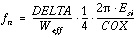
The narrow width effect is included through the f
n
parameter:
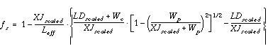
The term f
s
expresses the effect of the short channel and is determined as:

Effective Channel Length and Width
The model determines effective channel length and width in the LEVEL 3 model as follows:


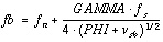
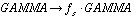
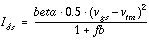
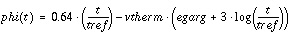
Threshold Voltage,
vth
The effective threshold voltage, including the device size and terminal voltage effects, is calculated by:
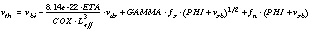
where:

or
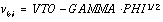
The VTO is the extrapolated zero-bias threshold voltage of a large device. If VTO, GAMMA, and PHI are not specified, Star-Hspice computes them (see Common Threshold Voltage Parameters).
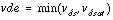
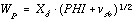
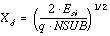
Saturation Voltage,
vdsat
For the LEVEL 3 model, Star-Hspice determines saturation voltage due to channel pinch-off at the drain side. The model uses the parameter VMAX to include the reduction of the saturation voltage due to carrier velocity saturation effect.

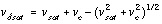
where:

The surface mobility parameter "us" is defined in the next section. If the model parameter VMAX is not specified, then:

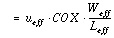
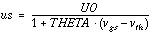
Effective Mobility,
ueff
The model defines the carrier mobility reduction due to the normal field as the effective surface mobility (us).
vgs>vth
The model determines the degradation of mobility due to the lateral field and the carrier velocity saturation if you specify the VMAX model parameter.
VMAX>0

otherwise,

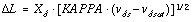
Channel Length Modulation
For vds>v
dsat
, the channel length modulation factor is computed. The model determines the channel length reduction  differently, depending on the VMAX model parameter value.
VMAX = 0
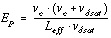
VMAX>0
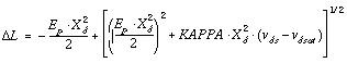
where E
p
is the lateral electric field at the pinch off point. Its value is approximated by:
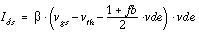
The current I
ds
in the saturation region is computed as:

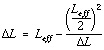
In order to prevent the denominator from going to zero, Star-Hspice limits the  value as follows:
If

then
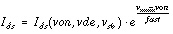
Subthreshold Current, I
ds
This region of operation is characterized by the model parameter for fast surface state (NFS). The modified threshold voltage (von) is determined as follows:
NFS>0

where:

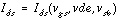
The current I
ds
is given by:
vgs<von

NOTE: The model does not use the modified threshold voltage in strong inversion.
If WIC=3, the model calculates subthreshold current differently. In this case, the I
ds
current is:

Subthreshold current isub for LEVEL=3 is the same as for LEVEL=13 (see Subthreshold Current ids).
N0eff and NDeff are functions of effective device width and length.
Compatibility Notes
This section describes compatibility issues.
Star-Hspice versus SPICE3
Differences between Star-Hspice and Berkeley SPICE3 can arise in the following situations:
Small XJ
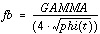
Star-Hspice and SPICE3 differ for small values of XJ, typically less than 0.05 microns. Such small values for XJ are physically unreasonable and should be avoided. XJ is used to calculate the short-channel reduction of the GAMMA effect,
f
s
is normally less than or equal to 1. For very small values of XJ, f
s
can be greater than one. Star-Hspice imposes the limit f
s
<=
1.0, while SPICE3 allows f
s
>1.0.
ETA
Star-Hspice uses 8.14 as the constant in the ETA equation, which provides the variation in threshold with v
ds
. Berkeley SPICE3 uses 8.15.
Solution:
To convert a SPICE3 model to Star-Hspice, multiply ETA by 815/814.
NSUB Missing
When NSUB is missing in SPICE3, the KAPPA equation becomes inactive. In Star-Hspice, a default NSUB is generated from GAMMA, and the KAPPA equation is active.
Solution:
If NSUB is missing in the SPICE3 model, set KAPPA=0 in the Star-Hspice model.
LD Missing
If LD is missing, Star-Hspice uses the default 0.75·XJ. SPICE3 defaults LD to zero.
Solution:
If LD is missing in the SPICE3 model, set LD=0 in the HSPICE model.
Constants
|
Boltzmann constant
|
k
|
= 1.3806226e-23J
·
K
-1
|
|
Electron charge
|
e
|
= 1.6021918e-19C
|
|
Permittivity of silicon dioxide
|

|
= 3.45314379969e-11F/m
|
|
Permittivity of silicon
|

|
= 1.035943139907e-10F/m
|
Temperature Compensation
The example below verifies temperature dependence for LEVEL 3.
Input file
$ test of temp dependence for LEVEL=3 Tlevc=0 Tlev=1
.option ingold=2 numdgt=6
.temp 25 100
vd d 0 5
vg g 0 2
m1 d g 0 0 nch w=10u L=1u
.op
.print id=lx4(m1) vdsat=lv10(m1)
.model nch nmos LEVEL=3 tlev=1 tlevc=0 acm=3
+ uo=600 tox=172.6572
+ vto=0.8 gamma=0.8 phi=0.64
+ kappa=0 xj=0
+ nsub=1e16 rsh=0
+ tcv=1.5e-3 bex=-1.5
.end
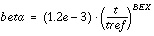
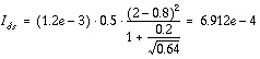
This simple model, with XJ=0 and KAPPA=0, has a saturation current:
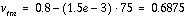
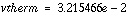
Using the model parameters in the input file and the equations from the previous page:
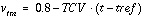
At room temperature:


At T=100:


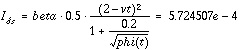
Star-Hspice results:
T=25, id=6.91200e-04
T=100, id=5.72451e-04
These results are in agreement with the hand calculations.
Star-Hspice Manual - Release 2001.2 - June 2001


