LEVEL 2 IDS: Grove-Frohman Model
This section describes the parameters and equations for the LEVEL 2 IDS: Grove-Frohman model.
LEVEL 2 Model Parameters
The LEVEL 2 model parameters follow.
Basic Model Parameters
|
Name (Alias)
|
Units
|
Default
|
Description
|
|
LEVEL
|
|
1.0
|
DC model selector. LEVEL 2 is the Grove-Frohman model.
|
|
COX
|
F/m
2
|
3.453e-4
|
Oxide capacitance per unit gate area. This parameter is calculated from TOX if not specified.
|
|
ECRIT (ESAT)
|
V/cm
|
0.0
|
Critical electric field for carrier velocity saturation. From Grove:electrons 6e4
holes 2.4e4
Use zero to indicate an infinite value. ECRIT is preferred over VMAX because the equation is more stable. ECRIT is estimated as:
ECRIT = 100
·
(VMAX / UO)
|
|
KP (BET, BETA)
|
A/V
2
|
2.0e-5
|
Intrinsic transconductance. If KP is not specified and UO and TOX are entered, KP is calculated from
KP = UO
·
COX
|
|
LAMBDA
(LAM, LA)
|
V
-1
|
0.0
|
Channel length modulation
|
|
NEFF
|
|
1.0
|
Total channel charge (fixed and mobile) coefficient
|
|
TOX
|
m
|
1e-7
|
Gate oxide thickness
|
|
VMAX (VMX, VSAT)
|
m/s
|
0.0
|
Maximum drift velocity of carriers. Use zero to indicate an infinite value.
|
Effective Width and Length Parameters
|
Name (Alias)
|
Units
|
Default
|
Description
|
|
DEL
|
m
|
0.0
|
Channel-length reduction on each side:
DELscaled = DEL
·
SCALM
|
|
LD (DLAT,
LADT)
|
m
|
|
Lateral diffusion into channel from source and drain diffusion.
If LD and XJ are unspecified, LD default=0.0.
When LD is unspecified but XJ is specified, LD is calculated from: XJ. The default=0.75
·
XJ.
LDscaled = LD
·
SCALM
|
|
LDAC
|
m
|
|
This parameter is the same as LD, but if LDAC is included in the .MODEL statement, it replaces LD in the Leff calculation for AC gate capacitance.
|
|
LMLT
|
|
1.0
|
Length shrink factor
|
|
LREF
|
m
|
0.0
|
Channel length reference
LREFscaled = LREF
·
SCALM
|
|
WD
|
m
|
0.0
|
Lateral diffusion into channel from bulk along width WDscaled = WD
·
SCALM
|
|
WDAC
|
m
|
|
This parameter is the same as WD, but if WDAC is included in the .MODEL statement, it replaces WD in the Weff calculation for AC gate capacitance.
|
|
WMLT
|
|
1.0
|
Diffusion layer and width shrink factor
|
|
WREF
|
m
|
0.0
|
Channel width reference
WREFscaled = WREF
·
SCALM
|
|
XJ
|
m
|
0.0
|
Metallurgical junction depth
XJscaled = XJ
·
SCALM
|
|
XL (DL,
LDEL)
|
m
|
0.0
|
Length bias accounts for masking and etching effects
XLscaled = XL
·
SCALM
|
|
XW (DW, WDEL)
|
m
|
0.0
|
Width bias accounts for masking and etching effects
XWscaled = XW
·
SCALM
|
Threshold Voltage Parameters
|
Name (Alias)
|
Units
|
Default
|
Description
|
|
DELTA
|
|
0.0
|
Narrow width factor for adjusting threshold
|
|
GAMMA
|
V
1/2
|
0.5276
|
Body effect factor. This parameter is calculated from NSUB if not specified (see Common Threshold Voltage Parameters).
|
|
LND
|
µm/V
|
0.0
|
ND length sensitivity
|
|
LN0
|
µm
|
0.0
|
N0 length sensitivity
|
|
ND
|
V
-1
|
0.0
|
Drain subthreshold factor
|
|
N0
|
|
0.0
|
Gate subthreshold factor. Typical value=1.
|
|
NFS (DFS, NF, DNF)
|
cm
-2
·
V
-1
|
0.0
|
Fast surface state density
|
|
NSUB (DNB, NB)
|
cm
-3
|
1e15
|
Bulk surface doping. If NSUB is not specified, it is calculated from GAMMA.
|
|
PHI
|
V
|
0.576
|
Surface inversion potential. If PHI is not specified, it is calculated from NSUB (see Common Threshold Voltage Parameters).
|
|
VTO(VT)
|
V
|
|
Zero-bias threshold voltage. If it is not specified, it is calculated (see Common Threshold Voltage Parameters).
|
|
WIC
|
|
0.0
|
Subthreshold model selector
|
|
WND
|
µm/V
|
0.0
|
ND width sensitivity.
|
|
WN0
|
µm
|
0.0
|
N0 width sensitivity
|
Mobility Parameters
|
Name (Alias)
|
Units
|
Default
|
Description
|
|
MOB
|
|
0.0
|
Mobility equation selector. This parameter can be set to MOB=0 or MOB=7. If MOB=7, the model is changed, which also affects the channel length calculation.
NOTE: MOB=7 operates as a flag. It invokes the channel length modulation and mobility equations of MOSFET LEVEL 3.
|
|
THETA
|
V
-1
|
0.0
|
Mobility modulation. THETA is used only when MOB=7. A typical value in this application is THETA=5e-2.
|
|
UCRIT
|
V/cm
|
1.0e4
|
Critical field for mobility degradation, UCRIT. The parameter is the limit at which the surface mobility UO begins to decrease in accordance with the empirical relation given later.
|
|
UEXP (F2)
|
|
0.0
|
Critical field exponent in the empirical formula which characterizes surface mobility degradation
|
|
UO (UB, UBO)
|
cm
2
/
(V·s)
|
600 (N)
250 (P)
|
Low-field bulk mobility. This parameter is calculated from KP if KP is input.
|
|
UTRA
|
|
0.0
|
Transverse field coefficient
NOTE: SPICE does not use UTRA. Star-Hspice uses it if supplied, but issues a warning because UTRA can hinder convergence.
|
The mobility parameters are best determined by curve fitting. In most cases UTRA should be specified between 0.0 and 0.5. Nonzero values for UTRA can result in negative resistance regions at the onset of saturation.
LEVEL 2 Model Equations
The LEVEL 2 model equations follow.
IDS Equations
The following section describes the way the LEVEL 2 MOSFET model calculates the drain current of n-channel and p-channel MOSFETs.
Cutoff Region, 
 (see subthreshold current)
On Region, vgs>vth
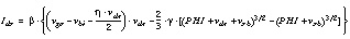
where:

Effective Channel Length and Width
The model calculates effective channel length and width from the drawn length and width as follows:


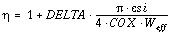
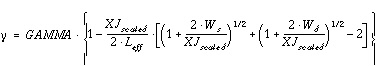
Threshold Voltage,
vth
The model parameter VTO is an extrapolated zero-bias threshold voltage of a large device. The effective threshold voltage, including the device size effects and the terminal voltages, is calculated by:
where:

The narrow width effect is included through vbi and  . To include the narrow width effect, specify the model parameter DELTA. The short-channel effect is included through the effective
  . To include short-channel effects, the model parameter XJ must be greater than zero. Then:
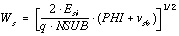
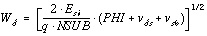
The depletion widths, W
s
and W
d
, are determined by:
Star-Hspice calculates parameters such as VTO, GAMMA, and PHI unless you specify them. The model uses these parameters to calculate threshold voltage. (See Common Threshold Voltage Parameters).
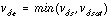
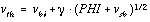
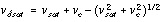
Saturation Voltage,
vdsat
If you do not specify the model parameter VMAX, the program computes the saturation voltage due to channel pinch off at the drain side. By including the corrections for small-size effects, vsat is:
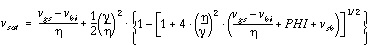

If you specify ECRIT, the program modifies vsat to include carrier velocity saturation effect.
where:

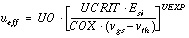
Mobility Reduction,
ueff
The mobility of carriers in the channel decreases as the carriers' speeds approach their scattering limited velocity. In Star-Hspice the mobility degradation for the LEVEL 2 MOS model uses two different equations, depending on the mobility equation selector value of MOB.
If MOB=0, (default):
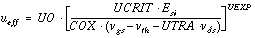
Since ueff is less than UO, the program uses the above equation if the bracket term is less than one; otherwise the program uses ueff=UO.
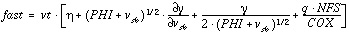
If MOB=7, THETA 0
0
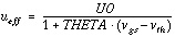
vgs<vth, ueff = UO
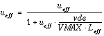
If MOB=7, THETA=0
If MOB=7, VMAX>0
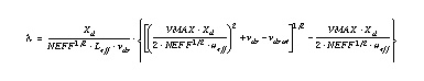
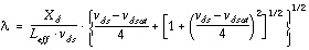
Channel Length Modulation
The LEVEL 2 MOS model includes the channel length modulation effect by modifying the I
ds
current as follows:

The model calculates the value of  if you do not specify the model parameter LAMBDA.
LAMBDA>0

VMAX>0, NSUB >0, and LAMBDA
VMAX=0, NSUB>0, and LAMBDA 
If MOB=0
If MOB=7
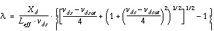
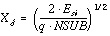
where X
d
is defined by:
The above equations do not include the effect of the field between gate and drain and gate and pinch-off point, respectively. They tend to overestimate the output conductance in the saturation region.
The modification of I
ds
by factor (1 -  · vds) is equivalent to replacing Leff with:
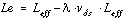
To prevent the channel length (Le) from becoming negative, Star-Hspice limits the value of Le.
If Le < xwb, then Le is replaced by:

where:

Subthreshold Current, I
ds
This region of operation is characterized by the fast surface states model parameter, NFS. For NFS>0 the model determines the modified threshold voltage (von) as follows:

where:
and vt is the thermal voltage.
The I
ds
current for vgs<von is given by:
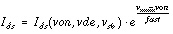

where:
NOTE: The modified threshold voltage (von), due to NFS specification, is also used in strong inversion instead of vth, mainly in the mobility equations.
If WIC=3, the model calculates the subthreshold current differently. In this case the I
ds
current is:

The N0eff and NDeff are functions of effective device width and length.
Star-Hspice Manual - Release 2001.2 - June 2001