


A transmission line or interconnect is one of the following:
Many applications model electrical properties of interconnections between nodes by their equivalent circuits, and integrate them into the system simulation to accurately predict system performance.
An electrical model that simulates the behavior of interconnect must consider all of the following:
You can choose from the following circuit models for interconnects:
Choosing the simplest model that adequately simulates the required performance minimizes sources of confusion and error during analysis.
Generally, to simulate both low and high frequency electrical properties of interconnects, select the U Element transmission line model. For compatibility with conventional versions of SPICE, use one a discrete lumped model or the T Element.
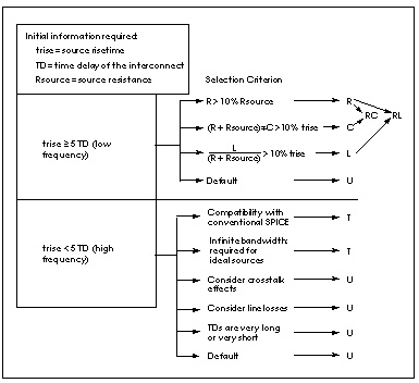
Following are the factors that determine the best choice of a transmission line:
trise = source risetime
Rsource = source output impedance
Z0 = characteristic impedance
TD = time delay of the interconnection
R = equivalent series resistance
C = equivalent shunt capacitor
L = equivalent series inductance
Wire Model Selection Chart shows you how to select a model based on source and interconnect properties.
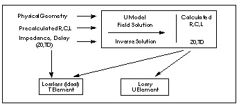
Use the U model with either the ideal T Element or the lossy U Element. You can also use the T Element alone, without the U model. Star-Hspice offers both, a flexible definition of the conventional SPICE T Element and an accurate U Element lossy simulation.
The T and U Elements do not support the <M=val> multiplier function. If a U or T Element is used in a subcircuit and an instance of the subcircuit has a multiplier applied, the results are inaccurate.
A warning message similar to the following is issued in both the status file (. st0 ) and the output file (. lis ) if the smallest transmission line delay is less than TSTOP/10e6:
**warning**: the smallest T-line delay (TD) = 0.245E-14 is too small
Please check TD, L and SCALE specification
This feature is an aid to finding errors that cause excessively long simulations.
All transmission lines have a ground reference for the signal conductors. In this manual, the ground reference is called the reference plane so that it is not confused with SPICE ground. The reference plane is the shield or the ground plane of the transmission line element. The reference plane nodes may or may not be connected to SPICE ground.
The ideal and lossy transmission line models each have particular advantages, and they may be used in a complementary manner. Both model types are fully functional in AC analysis and transient analysis. Some of the comparative advantages and uses of each type of model are listed in Ideal versus Lossy Transmission Line.
The ideal line is modeled as a voltage source and a resistor. The lossy line is modeled as a multiple lumped filter section, as shown in Ideal versus Lossy Transmission Line Model.
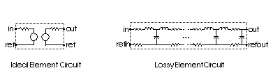
Because the ideal element represents the complex impedance as a resistor, the transmission line impedance is constant, even at DC values. On the other hand, you must prefilter the lossy element if ideal piecewise linear voltage sources are used to drive the line.
The U model allows three different description formats: geometric/physical, precomputed, and electrical. It provides equally natural description of vendor parts, physically described shapes, and parametric input from field solvers. The description format is specified by the required model parameter ELEV, as follows:
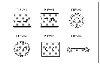
The U model explicitly supports transmission lines with several types of geometric structures. The geometric structure type is indicated by the PLEV model parameter, as follows:
The following Star-Hspice file fragment is an example of how both T Elements and U Elements can be referred to a single U model as indicated in U Model, T Element and U Element Relationship. The file specifies a 200 millimeter printed circuit wire implemented as both a U Element and a T Element. The two implementations share a U model that is a geometric description (ELEV=1) of a planar structure (PLEV=1).
T1 in gnd t_out gnd micro1 L=200m
U1 in gnd u_out gnd micro1 L=200m
.model micro1 U LEVEL=3 PLEV=1 ELEV=1 wd=2m ht=2m th=0.25m KD=5
The next section provides details of element and model syntax