


It is often necessary to review the basic transistor characteristics to diagnose a simulation or modeling problem. This demonstration file, $installdir/demo/hspice/mos/mosivcv.sp, is a template file that can be used with any MOS model. The example shows the easy input file creation and the complete graphical results display. The following features aid model evaluations:
This template provides the ability to get plots of internal variables such as:
|
i1, i2, i3, or i4 can specify the true branch currents for each transistor node |
|
|
Gate transconductance GM. (LX8 specifies GDS, and LX9 specifies GMB) |
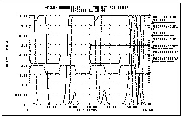
*FILE: MOSIVCV.SP IDS, VGS, CV AND GM PLOTS
.OPTIONS SCALE=1U DCCAP
.DC VDDN 0 5.0 .1 $VBBN 0 -3 -3 sweep supplies
.PARAM ww=8 LL=2
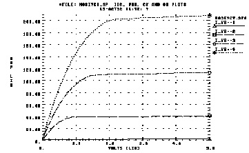
$ ids-vds curves
.GRAPH 'I_VG=1' =I(MN1) 'I_VG=2' =I(MN2) 'I_VG=3' =I(MN3)
+ 'I_VG=4' =I(MN4)
.GRAPH 'I_VG=-1'=I(MP1) 'I_VG=-2'=I(MP2) 'I_VG=-3'=I(MP3)
+ 'I_VG=-4'=I(MP4)
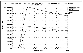
$ ids-VGs curves
.GRAPH 'I_VD=.5'=I(MN6) 'I_VD=-.5'=I(MP6)
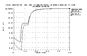
$ gate caps (cgs+cgd+cgb)
.GRAPH 'CG-TOT_N'=LX18(MN6) 'CG-TOT_P'= LX18(MP6)
$ gm
.GRAPH 'GM_N'=LX7(MN6) 'GM_P'=LX7(MP6)
VDDN vdd_n gnd 5.0
VBBN vbb_n gnd 0.0
EPD vdd_p gnd vdd_n gnd -1 $ reflect vdd for P devices
EPB vbb_p gnd vbb_n gnd -1 $ reflect vbb for P devices
V1 vg1 gnd 1
V2 vg2 gnd 2
V3 vg3 gnd 3
V4 vg4 gnd 4
V5 vddlow_n gnd .5
V-1 vg-1 gnd -1
V-2 vg-2 gnd -2
V-3 vg-3 gnd -3
V-4 vg-4 gnd -4
V-5 vddlow_p gnd -.5
MN1 vdd_n vg1 gnd vbb_n N W=ww L=LL
MN2 vdd_n vg2 gnd vbb_n N W=ww L=LL
MN3 vdd_n vg3 gnd vbb_n N W=ww L=LL
MN4 vdd_n vg4 gnd vbb_n N W=ww L=LL
MP1 gnd vg-1 vdd_p vbb_p P W=ww L=LL
MP2 gnd vg-2 vdd_p vbb_p P W=ww L=LL
MP3 gnd vg-3 vdd_p vbb_p P W=ww L=LL
MP4 gnd vg-4 vdd_p vbb_p P W=ww L=LL
MN6 vddlow_n vdd_n gnd vbb_n N W=ww L=LL
MP6 gnd vdd_p vddlow_p vbb_p P W=ww L=LL
.MODEL N NMOS LEVEL=3 VTO=0.7 UO=500 KAPPA=.25
+ KP=30U ETA=.01 THETA=.04 VMAX=2E5 NSUB=9E16 TOX=400
+ GAMMA=1.5 PB=0.6 JS=.1M XJ=0.5U LD=0.1U NFS=1E11
+ NSS=2E10 RSH=80 CJ=.3M MJ=0.5 CJSW=.1N MJSW=0.3
+ acm=2 capop=4
*
.MODEL P PMOS LEVEL=3 VTO=-0.8 UO=150 KAPPA=.25
+ KP=15U ETA=.015 THETA=.04 VMAX=5E4 NSUB=1.8E16 TOX=400
+ GAMMA=.67 PB=0.6 JS=.1M XJ=0.5U LD=0.15U NFS=1E11
+ NSS=2E10 RSH=80 CJ=.3M MJ=0.5 CJSW=.1N MJSW=0.3
+ acm=2 capop=4
.ENDStar-Hspice Manual - Release 2001.2 - June 2001