In Star-Hspice there are four voltage and current controlled elements, known as G, E, H and F Elements. You can use these controlled elements to model the following:
The controlled elements can be either linear or nonlinear functions of controlling node voltages or branch currents, depending on whether you used the polynomial or piecewise linear functions.
The functions of the G, E, F, and H controlled elements are different. The G Element can be a voltage or current controlled current source, a voltage controlled resistor, a piecewise linear voltage controlled capacitor, an ideal delay element, or a piecewise linear multi-input AND, NAND, OR, or NOR gate.
The E Elements can be a voltage or current controlled voltage source, an ideal op-amp, an ideal transformer, an ideal delay element, or a piecewise linear voltage controlled multi-input AND, NAND, OR, or NOR gate.
The H Element can be a current controlled voltage source, an ideal delay element, or a piecewise linear current controlled multi-input AND, NAND, OR, or NOR gate.
The F Element can be a current controlled current source, an ideal delay element, or a piecewise linear current controlled multi-input AND, NAND, OR, or NOR gate.
Polynomial and piecewise linear functions are discussed below. Element statements for linear or nonlinear functions are described in the following sections.
The controlled element statement allows the definition of the controlled output variable (current, resistance, or voltage) as a polynomial function of one or more voltages or branch currents. There are three polynomial equations that can be selected through the POLY(ndim) parameter in the E, F, G, or H Element statement.
POLY(1) one-dimensional equation
POLY(2) two-dimensional equation
POLY(3) three-dimensional equation
The POLY(1) polynomial equation specifies a polynomial equation as a function of one controlling variable, POLY(2) as a function of two controlling variables, and POLY(3) as a function of three controlling variables.
Along with each polynomial equation are polynomial coefficient parameters (P0, P1 ... Pn) that can be set to explicitly define the equation.
If the function is one-dimensional, that is, a function of one branch current or node voltage, the function value FV is determined by the following expression:
FV the controlled voltage or current from the controlled source
P0. . .Pn coefficients of polynomial equation
FA the controlling branch current or nodal voltage
The following controlled source statement is an example of a one-dimensional function:
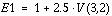
The above voltage controlled voltage source is connected to nodes 5 and 0. The single dimension polynomial function parameter, POLY(1), informs Star-Hspice that E1 is a function of the difference of one nodal voltage pair, in this case, the voltage difference between nodes 3 and 2, hence FA=V(3,2). The dependent source statement then specifies that P0=1 and P1=2.5. From the one-dimensional polynomial equation above, the defining equation for E1 is:
Where the function is two-dimensional, that is, a function of two node voltages or two branch currents, FV is determined by the following expression:
For a two-dimensional polynomial, the controlled source is a function of two nodal voltages or currents. To specify a two-dimensional polynomial, set POLY(2) in the controlled source statement.
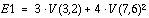
For example, generate a voltage controlled source that gives the controlled voltage, E1, as:
To implement this function, use the following controlled source element statement:
E1 1 0 POLY(2) 3 2 7 6 0 3 0 0 0 4
This specifies a controlled voltage source connected between nodes 1 and 0 that is controlled by two differential voltages: the voltage difference between nodes 3 and 2 and the voltage difference between nodes 7 and 6, that is, FA=V(3,2) and FB=V(7,6). The polynomial coefficients are P0=0, P1=3, P2=0, P3=0, P4=0, and P5=4.
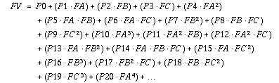
For a three-dimensional polynomial function with arguments FA, FB, and FC, the function value FV is determined by the following expression:
For example, generate a voltage controlled source that gives the voltage as:
From the above defining equation and the three-dimensional polynomial equation:
Substituting these values into the voltage controlled voltage source statement:
E1 1 0 POLY(3) 3 2 7 6 9 8 0 3 0 0 0 0 0 4 0 0 0 0 0 0 0 0 0 + 0 0 5
The above specifies a controlled voltage source connected between nodes 1 and 0 that is controlled by three differential voltages: the voltage difference between nodes 3 and 2, the voltage difference between nodes 7 and 6, and the voltage difference between nodes 9 and 8, that is, FA=V(3,2), FB=V(7,6), and FC=V(9,8). The statement gives the polynomial coefficients as P1=3, P7=4, P19=5, and the rest are zero.
The one-dimensional piecewise linear (PWL) function allows designers to model some special element characteristics, such as those of tunnel diodes, silicon controlled rectifiers. and diode breakdown regions. You can describe the piecewise linear function by specifying measured data points. Although the device characteristic is described by data points, Star-Hspice automatically smooths the corners to ensure derivative continuity and, as a result, better convergence.
A parameter DELTA is provided to control the curvature of the characteristic at the corners. The smaller the DELTA, the sharper the corners are. The maximum value allowed for DELTA is half the smallest of the distances between breakpoints. Specify a DELTA that provides satisfactory sharpness of the function corners. You can specify up to 100 breakpoint pairs. You must specify at least two point pairs (with each point consisting of an x and a y coefficient).
The functions NPWL and PPWL can be used for modeling bidirectional switch or transfer gates using G Elements. The NPWL and PPWL functions behave like NMOS and PMOS transistors.
The piecewise linear function also is used to model multi-input AND, NAND,OR, and NOR gates. In this case only one input determines the state of the output. In AND and NAND gates, the input with the smallest value is used in the piecewise linear function to determine the corresponding output of the gates. In the OR and NOR gates, the input with the largest value is used to determine the corresponding output of the gates.
Star-Hspice Manual - Release 2001.2 - June 2001