Linear
Exxx n+ n- <VCVS> in+ in- gain <MAX=val> <MIN=val> <SCALE=val>
+ <TC1=val> <TC2=val><ABS=1> <IC=val>
Polynomial
Exxx n+ n- <VCVS> POLY(ndim) in1+ in1- ... inndim+ inndim-<TC1=val>
+ <TC2=val> <SCALE=val><MAX=val><MIN=val> <ABS=1> p0 <p1...>
+ <IC=vals>
Piecewise Linear
Exxx n+ n- <VCVS> PWL(1) in+ in- <DELTA=val> <SCALE=val> <TC1=val>
+ <TC2=val> x1,y1 x2,y2 ... x100,y100 <IC=val>
Multi-Input Gates
Exxx n+ n- <VCVS> gatetype(k) in1+ in1- ... inj+ inj- <DELTA=val> <TC1=val>
+ <TC2=val> <SCALE=val> x1,y1 ... x100,y100 <IC=val>
Delay Element
Exxx n+ n- <VCVS> DELAY in+ in- TD=val <SCALE=val> <TC1=val> <TC2=val>
+ <NPDELAY=val>
Exxx n+ n- VOL='equation' <MAX>=val> <MIN=val>
Exxx n+ n- OPAMP in+ in-
Exxx n+ n- TRANSFORMER in+ in- k
ABS Output is absolute value if ABS=1.
DELAY Keyword for the delay element. The delay element is the same as voltage controlled voltage source, except it is associated by a propagation delay TD.This element facilitates the adjustment of propagation delay in the subcircuit modeling process. DELAY is a Star-Hspice keyword and should not be used as a node name.
DELTA Used to control the curvature of the piecewise linear corners. Defaults to 1/4 of the smallest of the distances between breakpoints. The maximum is 1/2 of the smallest of the distances between breakpoints.
Exxx Voltage controlled element name. Must begin with "E", which may be followed by up to 15 alphanumeric characters.
IC Initial condition: the initial estimate of the value(s) of the controlling voltage(s). Default=0.0.
in +/- Positive or negative controlling nodes. Specify one pair for each dimension.
j Ideal transformer turn ratio: 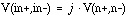
MAX Maximum output voltage value. The default is undefined, and sets no maximum value.
MIN Minimum output voltage value. The default is undefined, and sets no minimum value.
n+/- Positive or negative node of controlled element.
NPDELAY Sets the number of data points to be used in delay simulations. The default value is the larger of 10 or the smaller of TD/tstep and tstop/tstep. That is,
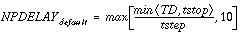
The values of tstep and tstop are specified in the .TRAN statement.
OPAMP Keyword for ideal op-amp element. OPAMP is a Star-Hspice keyword and should not be used as a node name.
p0, p1 ... Polynomial coefficients. When one coefficient is specified, Star-Hspice assumes it to be p1, with p0=0.0, and the element is linear. When more than one polynomial coefficient is specified by p0, p1, p2, ..., the element is nonlinear. See Polynomial Functions.
POLY Polynomial dimension. If POLY(ndim) is not specified, a one-dimensional polynomial is assumed. Ndim must be a positive number.
PWL Piecewise linear function keyword.
SCALE Element value multiplier.
TC
1, TC2
First and second order temperature coefficients. The SCALE is updated by temperature:

TRANS FORMER Keyword for ideal transformer. TRANSFORMER is a Star-Hspice keyword and should not be used as a node name.
VCVS Keyword for voltage controlled voltage source. VCVS is a Star-Hspice keyword and should not be used as a node name.
A voltage amplifier with supply limits can be built with the voltage controlled voltage source. The output voltage across nodes 2,3 = v(14,1) * 2. The voltage gain parameter, 2, is also given. The MAX and MIN parameters specify a maximum E1 voltage of 5V and a minimum E1 voltage output of -5V. If, for instance, V(14,1) = -4V, E1 would be set to -5V and not -8V as the equation would produce.
Eopamp 2 3 14 1 MAX=+5 MIN=-5 2.0
A user-defined parameter may be used in the following format to specify a value for polynomial coefficient parameters:
.PARAM CU = 2.0
E1 2 3 14 1 MAX=+5 MIN=-5 CU
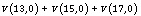
An ideal voltage summer specifies the source voltage as a function of three controlling voltage(s): V(13,0), V(15,0) and V(17,0). It describes a voltage source with the value:
This example represents an ideal voltage summer. The three controlling voltages are initialized for a DC operating point analysis to 1.5, 2.0, and 17.25 V, respectively.
EX 17 0 POLY(3) 13 0 15 0 17 0 0 1 1 1 IC=1.5,2.0,17.25
The voltage controlled source can also output a nonlinear function using the one-dimensional polynomial. Since the POLY parameter is not specified, a one-dimensional polynomial is assumed, i.e., a function of one controlling voltage. The equation corresponds to the element syntax. Behavioral equations replace this older method.
	E2 3 4 VOLT = "10.5 + 2.1 *V(21,17) + 1.75 *V(21,17)2
"
E2 3 4 POLY 21 17 10.5 2.1 1.75
A simple inverter with no delay can be built with a piecewise linear transfer function.
Einv out 0 PWL(1) in 0 .7v,5v 1v,0v
With the turn ratio 10 to 1, the voltage relationship is V(out)=V(in)/10.
Etrans out 0 TRANSFORMER in 0 10
Voltage Controlled Oscillator (VCO)
The keyword VOL is used to define a single-ended input that controls the output of a VCO.
In the following example, the frequency of the sinusoidal output voltage at node "out" is controlled by the voltage at node "control". Parameter "v0" is the DC offset voltage and "gain" is the amplitude. The output is a sinusoidal voltage with a frequency of freq*control.
Evco out 0 VOL='v0+gain*SIN(6.28*freq*v(control)*TIME)'Star-Hspice Manual - Release 2001.2 - June 2001