


Behavioral elements offer a higher level of abstraction and a faster processing time over the lower level description of an analog function. For system-level designers, function libraries of subcircuits containing these elements are used to describe parts such as op-amps, vendor specific output buffer drivers, TTL drivers, logic-to-analog and analog-to-logic simulator converters. For the integrated circuit designer, these elements offer a fast representation that is particularly useful in filter and signal processing design.
Behavioral elements are based on using an arbitrary algebraic equation as a transfer function to a voltage (E) or current (G) source. This function can include nodal voltages, element currents, time, or user defined parameters. A good example of this is a VCO where "control" is the input voltage node and "osc" is the oscillator output:
Evco osc 0 VOL='voff+gain*SIN(6.28*freq*(1+V(control))*TIME)'
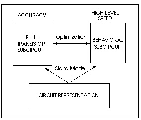
Subcircuits provide a way to encapsulate a function. If you split the function definition from the use, you create a a hierarchy. If you pass parameters into the subcircuit, you create a parameterized cell. If you create a full transistor cell library and a behavioral representation library, you can deal with mixed signal functions within Star-Hspice. You can calibrate the behavioral elements from a full transistor circuit using the built-in OPTIMIZE function.
Controlled sources model both analog and digital circuits at the behavioral level, allowing for fast mixed-signal simulation times and providing a means to model system level operations. Controlled sources model gate switching action for the behavioral modeling of digital circuits. For analog behavioral modeling, the controlled sources can be programmed as mathematical functions that are either linear or nonlinear, dependent on other nodal voltages and branch currents.
Complex transition files are difficult to process using the piecewise linear sources. You can use the U Element A2D and D2A conversion functions to simplify processing of transition files. The A2D function converts analog output to digital data, and the D2A function converts digital input data to analog. You can export output to logic or VHDL simulators as well.
The examples of analog and digital elements in this chapter give some insight into how the behavioral elements operate.
Operational amplifiers are automatically designed using the subcircuit generator to meet given electrical specifications, such as PSRR, CMRR, and Vos. The generator produces component values for each of the elements in the design. The subcircuits produced by combining these values offer faster simulation times than conventional circuit level implementations.
Use the Discrete Device Library of standard industry IC components to model board level designs that contain transistors, diodes, opamps, comparators, converters, IC pins, printed circuit board traces and coaxial cables. You can model drivers and receivers to analyze transmission line effects and power and signal line noise.
Star-Hspice Manual - Release 2001.2 - June 2001