LEVEL 28 Modified BSIM Model
This section lists the LEVEL 28 parameters and equations for the modified BSIM model.
LEVEL 28 Features
The following are the significant features of the LEVEL 28 model.
-
Vertical field dependence of carrier mobility
-
Carrier velocity saturation
-
Drain-induced barrier lowering
-
Depletion charge sharing by source and drain
-
Nonuniform doping profile for ion-implanted devices
-
Channel length modulation
-
Subthreshold conduction
-
Geometric dependence of electrical parameters
LEVEL 28 Model Parameters
The LEVEL 28 model parameters follow.
Transistor Process Parameters
|
Name (Alias)
|
Units
|
Default
|
Description
|
|
LEVEL
|
|
1
|
MOSFET model level selector. Set this parameter to 28 for this Star-Hspice model.
|
|
B1
|
|
0.0
|
Lower vdsat transition point
|
|
LB1
|
µm
|
0.0
|
Length sensitivity
|
|
WB1
|
µm
|
0.0
|
Width sensitivity
|
|
B2
|
|
1
|
Upper vdsat transition point
|
|
LB2
|
µm
|
0.0
|
Length sensitivity
|
|
WB2
|
µm
|
0.0
|
Width sensitivity
|
|
CGBO
|
F/m
|
2.0e-10
|
Gate-to-bulk parasitic capacitance (F/m of length)
|
|
CGDO
|
F/m
|
1.5e-9
|
Gate-to-drain parasitic capacitance (F/m of width)
|
|
CGSO
|
F/m
|
1.5e-9
|
Gate-to-source parasitic capacitance (F/m of width)
|
|
ETA0
|
|
0.0
|
Linear vds threshold coefficient
|
|
LETA
|
µm
|
0.0
|
Length sensitivity
|
|
WETA
|
µm
|
0.0
|
Width sensitivity
|
|
ETAMN
|
|
0.0
|
Minimum linear vds threshold coefficient
|
|
LETAMN
|
µm
|
0.0
|
Length sensitivity
|
|
WETAMN
|
µm
|
0.0
|
Width sensitivity
|
|
GAMMN
|
V
1/2
|
0.0
|
Minimum root-vsb threshold coefficient
|
|
LGAMN
|
V
1/2
·µm
|
0.0
|
Length sensitivity
|
|
WGAMN
|
V
1/2
·µm
|
0.0
|
Width sensitivity
|
|
K1
|
V1/2
|
0.5
|
Root-vsb threshold coefficient
|
|
LK1
|
V1/2·µm
|
0.0
|
Length sensitivity
|
|
WK1
|
V1/2·µm
|
0.0
|
Width sensitivity
|
|
K2
|
|
0.0
|
Linear vsb threshold coefficient
|
|
LK2
|
µm
|
0.0
|
Length sensitivity
|
|
WK2
|
µm
|
0.0
|
Width sensitivity
|
|
MUZ
|
cm2/V·s
|
600
|
Low drain field first order mobility
|
|
LMUZ
|
µm
·
cm2/V·s
|
0.0
|
Length sensitivity
|
|
WMUZ
|
µm
·
cm2/V·s
|
0.0
|
Width sensitivity
|
|
N0
|
|
200
|
Low field weak inversion gate drive coefficient (value of 200 for N0 disables weak inversion calculation)
|
|
LN0
|
µm
|
0.0
|
Length sensitivity
|
|
WN0
|
µm
|
0.0
|
Width sensitivity
|
|
NB0
|
|
0.0
|
Vsb reduction to low field weak inversion gate drive coefficient
|
|
LNB
|
µm
|
0.0
|
Length sensitivity
|
|
WNB
|
µm
|
0.0
|
Width sensitivity
|
|
ND0
|
|
0.0
|
Vds reduction to low field weak inversion gate drive coefficient
|
|
LND
|
µm
|
0.0
|
Length sensitivity
|
|
WND
|
µm
|
0.0
|
Width sensitivity
|
|
PHI0
|
V
|
0.7
|
Two times the Fermi potential
|
|
LPHI
|
V·µm
|
0.0
|
Length sensitivity
|
|
WPHI
|
V·µm
|
0.0
|
Width sensitivity
|
|
TOXM (TOX)
|
µm (m)
|
0.02
|
Gate oxide thickness (if TOXM or TOX > 1, Angstroms is assumed)
|
|
U00
|
1/V
|
0.0
|
Gate field mobility reduction factor
|
|
LU0
|
µm/V
|
0.0
|
Length sensitivity
|
|
WU0
|
µm/V
|
0.0
|
Width sensitivity
|
|
U1
|
1/V
|
0.0
|
Drain field mobility reduction factor
|
|
LU1
|
µm/V
|
0.0
|
Length sensitivity
|
|
WU1
|
µm/V
|
0.0
|
Width sensitivity
|
|
VDDM
|
V
|
5.0
|
Critical voltage for high drain field mobility reduction
|
|
VFB0 (VFB)
|
V
|
-0.3
|
Flatband voltage
|
|
LVFB
|
V·µm
|
0.0
|
Length sensitivity
|
|
WVFB
|
V·µm
|
0.0
|
Width sensitivity
|
|
WFAC
|
|
4
|
Weak inversion factor
|
|
LWFAC
|
µm
|
0.0
|
Length sensitivity
|
|
WWFAC
|
µm
|
0.0
|
Width sensitivity
|
|
WFACU
|
|
0.0
|
Second weak inversion factor
|
|
LWFACU
|
µm
|
0.0
|
Length sensitivity
|
|
WWFACU
|
µm
|
0.0
|
Width sensitivity
|
|
X2E
|
1/V
|
0.0
|
Vsb correction to linear vds threshold coefficient
|
|
LX2E
|
µm/V
|
0.0
|
Length sensitivity
|
|
WX2E
|
µm/V
|
0.0
|
Width sensitivity
|
|
X2M (X2MZ)
|
cm2/V2·s
|
0.0
|
Vsb correction to low field first order mobility
|
|
LX2M (LX2MZ)
|
µm·cm
2
/V2
·s
|
0.0
|
Length sensitivity
|
|
WX2M (WX2MZ)
|
µm·cm
2
/V2
·s
|
0.0
|
Width sensitivity
|
|
X2U0
|
1/V
2
|
0.0
|
Vsb reduction to GATE field mobility reduction factor
|
|
LX2U0
|
µm/V
2
|
0.0
|
Length sensitivity
|
|
WX2U0
|
µm/V
2
|
0.0
|
Width sensitivity
|
|
X2U1
|
µm/V
2
|
0.0
|
Vsb reduction to DRAIN field mobility reduction factor
|
|
LX2U1
|
µm
2
/V
2
|
0.0
|
Length sensitivity
|
|
WX2U1
|
µm
2
/V
2
|
0.0
|
Width sensitivity
|
|
X33M
|
cm
2
/V
2
·s
|
0.0
|
Gate field reduction of X3MS
|
|
LX33M
|
µm·cm
2
/V
2
·s
|
0.0
|
Length sensitivity
|
|
WX33M
|
µm·cm
2
/V
2
·s
|
0.0
|
Width sensitivity
|
|
X3E
|
1/V
|
0.0
|
Vds correction to linear vds threshold coefficient
|
|
LX3E
|
µm/V
|
0.0
|
Length sensitivity
|
|
WX3E
|
µm/V
|
0.0
|
Width sensitivity
|
|
X3MS
|
cm
2
/V
2
·s
|
5.0
|
Vds correction for high drain field mobility
|
|
LX3MS
|
µm·cm
2
/V
2
·s
|
0.0
|
Length sensitivity
|
|
WX3MS
|
µm·cm
2
/V
2
·s
|
0.0
|
Width sensitivity
|
|
X3U1
|
1/V
2
|
0.0
|
Vds reduction to drain field mobility reduction factor
|
|
LX3U1
|
µm/V
2
|
0.0
|
Length sensitivity
|
|
WX3U1
|
µm/V
2
|
0.0
|
Width sensitivity
|
|
XPART
|
|
1.0
|
Selector for gate capacitance charge sharing coefficient
|
Notes:
1. When reading parameter names, be aware of the difference in appearance between the capital letter O, and the number zero 0.
2. All LEVEL 28 parameters should be specified using NMOS conventions, even for PMOS--for example, ETA0 = 0.02, not ETA0 = -0.02.
3. The WL-product sensitivity parameter is available for any parameter with an L and W sensitivity. Replace the leading "L" of the L sensitivity parameter name with a "P".
Basic Model Parameters
|
Name (Alias)
|
Units
|
Default
|
Description
|
|
LD (DLAT, LATD)
|
m
|
|
Lateral diffusion into channel from source and drain diffusion.
If LD and XJ are unspecified, the LD default=0.0.
When LD is unspecified but XJ is specified, LD is calculated from XJ. The LD default=0.75 XJ.
LDscaled = LD · SCALM
|
|
LDAC
|
m
|
|
This parameter is the same as LD, but if LDAC is included in the .MODEL statement, it replaces LD in the Leff calculation for AC gate capacitance.
|
|
LMLT
|
|
1.0
|
Length shrink factor
|
|
LREF
|
m
|
0.0
|
Reference channel length
LREFscaled = LREF · SCALM
|
|
XLREF
|
m
|
0.0
|
Difference between physical (on wafer) and drawn reference channel length
XLREFscaled = XLREF
·
SCALM
|
|
WD
|
m
|
0.0
|
Lateral diffusion into channel from bulk along width
WDscaled = WD · SCALM
|
|
WDAC
|
m
|
|
This parameter is the same as WD, but if WDAC is in the .MODEL statement, it replaces WD in the Weff calculation for AC gate capacitance.
|
|
WMLT
|
|
1.0
|
Diffusion layer and width shrink factor
|
|
XL (DL, LDEL)
|
m
|
0.0
|
Accounts for masking and etching effects
XLscaled = XL · SCALM
|
|
XW (DW, WDEL)
|
m
|
0.0
|
Accounts for masking and etching effects
XWscaled = XW · SCALM
|
|
WREF
|
m
|
0.0
|
Reference channel width
WREFscaled = WREF · SCALM
|
|
XWREF
|
m
|
0.0
|
Difference between physical (on wafer) and drawn reference channel width
XWREFscaled = XWREF
·
SCALM
|
Temperature Parameters
|
Name (Alias)
|
Units
|
Default
|
Description
|
|
BEX
|
|
-1.5
|
Temperature exponent for MUZ, X2M, X3MS, X33M mobility parameters
|
|
FEX
|
|
0.0
|
Temperature exponent for mobility reduction factor U1
|
|
TCV
|
V/°K
|
0.0
|
Flat-band voltage temperature coefficient
|
Sensitivity Factors of Model Parameters
For transistors, the L (channel length), W (channel width), and WL-product sensitivity factors of a basic electrical parameter are denoted by adding the characters L, W, and P, respectively, at the start of the name, and often dropping any ending "0". For example, VFB0 sensitivity factors are LVFB, WVFB, and PVFB. If A0 is a basic parameter, LA, WA and PA are the corresponding sensitivity factors of this parameter (note that LA, WA and PA cannot be scaled using option SCALM in Star-Hspice). Then the model uses the following general formula to obtain the parameter value.
The left side of the equation represents the effective model parameter value after device size adjustment. All the effective model parameters are in lower case and start with the character z, followed by the parameter name.
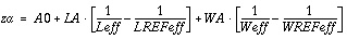
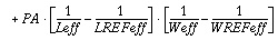
LA and WA are specified in units of microns times the units of A0. PA is specified in units of square microns times the units of A0.
If you set LREF or WREF=0, you effectively set the parameter to infinity. This is the default.
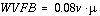
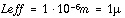
Example


LEVEL 28 Model Equations
The LEVEL 28 model equations follow.
Effective Channel Length and Width
The effective channel length and width for LEVEL 28 is determined to be consistent with the LEVEL 3 model. L, W and the multiplier M are from the .MODEL statement in the netlist. SCALE and SCALM are options. When no scaling options or multipliers are used,
Leff = L+XL-2·LD Weff = W+XW-2·WD
NOTE: If LDAC and WDAC are included in the .MODEL statement,
Leff=L+XL-2·LDAC Weff=W+XW-2·WDAC
Syntax
Lscaled = L·SCALE
Wscaled = W·SCALE
XLscaled = XL·SCALM
LDscaled = LD·SCALM
XWscaled = XW·SCALM
WDscaled = WD·SCALM
Leff = Lscaled·LMLT+XLscaled-2·LDscaled
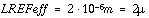
LREFeff = LREFscaled·LMLT+XLREFscaled-2·LDscaled
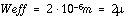
Weff = M·(Wscaled·WMLT+XWREFscaled-2·WDscaled)
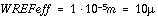
WREFeff = M·(WREFscaled·WMLT+XWscaled-2·WDscaled)
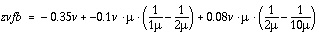
Threshold Voltage
Effective model parameter values for threshold voltage after device size adjustment are zphi, zvfb, zk1, zk2, zeta, zx2e, zx3e, zgammn, and zetamn. They are calculated from the model parameters PHI0, VFB0, K1, K2, ETA0, X2E, X3E, GAMMN, ETAMN, and their respective length and width sensitivity parameters.
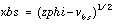
xbs=(zphi-vbs)
1/2
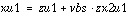
xeta=zeta+zx2e·vbs+zx3e·vds
vth=zvfb + zphi + zk1·xbs - zk2·xbs
2
-xeta·vds
This equation is quadratic in xbs and vds. It is joined to linear equations at d(vth)/d(xbs) = zgammn and at d(vth)/d(vds) = -zetamn, which prevents the quadratics from going in the wrong direction.
Both gammn and etamn default to zero and typically do not affect behavior in the normal operating region.
Effective Mobility
The effective model parameter values for mobility after device size adjustment are zmuz, zx2m, zx3m, zx33m, zu0, and zx2u0. They are calculated from the model parameters MUZ, X2M, X3m, X33M, U00, X2U0, and their respective length and width sensitivity parameters.


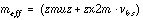

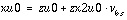
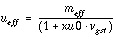
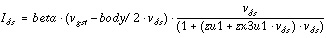
Saturation Voltage (vdsat)
The effective model parameter values for saturation voltage after device size adjustment are zu1, zx2u1, and zx3u1. They are calculated from the model parameters U1, X2U1, X3U1 and their respective length and width sensitivity parameters.
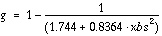
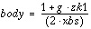

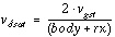
This is the value of vds that makes the partial derivative of
with respect to vds equal to zero.
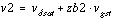
Transition Points
The effective model parameter values for transition points after device size adjustment are zb1 and zb2. They are calculated from the model parameters B1, B2, and their respective length and width sensitivity parameters.
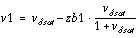
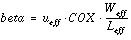
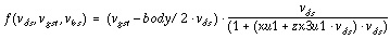
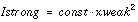
Strong Inversion Current
For vds < v1,
The vds derivative varies approximately linearly between v1 and v2.
For vds>v2, ids is a function of beta and vgst only. If zb1 and zb2 are both positive, their main effect is to increase the current in saturation.
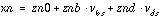
Weak Inversion Current
The effective model parameter values for weak inversion current after device size adjustment are zn0, znb, znd, zwfac and zwfacu. They are calculated from the model parameters N0, ND0, NB0, WFAC, WFACU, and their respective length and width sensitivity parameters.
The weak inversion current is calculated when zn0 is less than 200. It is added to the strong inversion current,
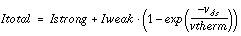
In deep subthreshold,

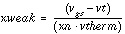
The modification of this formula near threshold is controlled by zwfac and zwfacu. Just above threshold, the device is in saturation:
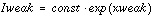
so Iweak needs an xweak
2
term to cancel the kink in gm at threshold. Then Iweak goes to zero for xweak>A0, which is at a small voltage above threshold. Iweak has four regions:
(1) xweak < -zwfac+A0

(2) -zwfac+A0 < xweak < 0

where wf is the integral with respect to xweak of

(3) 0 < xweak < A0

(4) A0 < xweak

A0 and the constants in the formulas above are not model parameters, but are uniquely determined by continuity conditions at the boundaries between regions.
Star-Hspice Manual - Release 2001.2 - June 2001


