LEVEL 8 IDS Model
The LEVEL 8 model, derived from research at Intersil and General Electric, is an enhanced version of the LEVEL 2 ids equation. LEVEL 2 differs from LEVEL 8 in the following areas: the effective substrate doping, threshold voltage, effective mobility, channel length modulation, and subthreshold current.
LEVEL 8 Model Parameters
This section lists the LEVEL 8 model parameters.
Basic DC Model Parameters
|
Name (Alias)
|
Units
|
Default
|
Description
|
|
LEVEL
|
|
1.0
|
IDS equation selector. Use LEVEL 8 for the advanced model using finite differences.
|
|
COX
|
F/m
2
|
3.45314e-4
|
Oxide capacitance per unit gate area. This parameter is calculated from TOX if not specified.
|
|
ECRIT (ESAT)
|
V/cm
|
0.0
|
Critical electric field for carrier velocity saturation, from Grove:
electrons 6e4
holes 2.4e4
Use zero to indicate an infinite value.
|
|
SNVB
|
1/
(V·cm
3
)
|
0.0
|
Slope of doping concentration versus vsb (element parameter). (Multiplied by 1e6)
|
|
TOX
|
m
|
1e-7
|
Oxide thickness
|
|
VMAX (VMX, VSAT)
|
m/s
|
0.0
|
Maximum drift velocity of carriers. Use zero to indicate an infinite value.
|
Effective Channel Width and Length Parameters
|
Name (Alias)
|
Units
|
Default
|
Description
|
|
DEL
|
m
|
0.0
|
Channel length reduction on each side. DEL is applicable in most MOSFET models. An exception is the BSIM (LEVEL 13) model, where DEL is not present.
DELscaled = DEL
·
SCALM
|
|
LD (DLAT, LATD)
|
m
|
|
Lateral diffusion into channel from source and drain diffusion. If LD and XJ are unspecified, LD default=0.0.
When LD is unspecified, but XJ is specified,
LD default=0.75
·
XJ. LDscaled = LD
·
SCALM.
|
|
LDAC
|
m
|
|
This parameter is the same as LD, but if LDAC is included in the .MODEL statement, it replaces LD in the Leff calculation for AC gate capacitance.
|
|
WD
|
m
|
0.0
|
Lateral diffusion into channel from bulk along width
WDscaled = WD
·
SCALM
|
|
WDAC
|
m
|
|
This parameter is the same as WD, but if WDAC is included in the .MODEL statement, it replaces WD in the Weff calculation for AC gate capacitance.
|
|
LMLT
|
|
1.0
|
Length shrink factor
|
|
LREF
|
m
|
0.0
|
Channel length reference
LREFscaled = LREF
·
SCALM
|
|
WMLT
|
|
1.0
|
Diffusion layer and width shrink factor
|
|
WREF
|
m
|
0.0
|
Channel width reference
WREFscaled = WREF
·
SCALM
|
|
XJ
|
m
|
0.0
|
Metallurgical junction depth
XJscaled = XJ
·
SCALM
|
|
XL (DL, LDEL)
|
m
|
0.0
|
Accounts for masking and etching effects
XLscaled = XL · SCALM
|
|
XW (WDEL, DW)
|
m
|
0.0
|
Accounts for masking and etching effects
XWscaled = XW
·
SCALM
|
Threshold Voltage Parameters
|
Name (Alias)
|
Units
|
Default
|
Description
|
|
CAV
|
|
0.0
|
Thermal voltage multiplier for the weak inversion equation
|
|
DELTA
|
|
0.0
|
Narrow width factor for adjusting threshold
|
|
ETA
|
|
0.0
|
Drain-induced barrier lowering (DIBL) effect coefficient for threshold voltage
|
|
GAMMA
|
V
1/2
|
|
Body effect factor. This parameter is calculated from NSUB if not specified (see Common Threshold Voltage Parameters).
|
|
LND
|
µ
m/V
|
0.0
|
ND length sensitivity
|
|
LN0
|
µ
m
|
0.0
|
N0 length sensitivity
|
|
ND
|
1/V
|
0.0
|
Drain subthreshold factor (typical value=1)
|
|
N0
|
|
0.0
|
Gate subthreshold factor (typical value=1)
|
|
WIC
|
|
0.0
|
Sub-threshold model selector
|
|
WND
|
µ
m/
V
|
0.0
|
ND width sensitivity
|
|
WN0
|
µ
m
|
0.0
|
N0 width sensitivity
|
|
NFS (DFS, NF, DNF)
|
cm
-2
·
V
-1
|
0.0
|
Fast surface state density
|
|
NSUB (DNB, NB)
|
cm
-3
|
1e15
|
Bulk surface doping. This parameter is calculated from GAMMA if not specified.
|
|
PHI
|
V
|
0.576
|
Surface inversion potential. This parameter is calculated from NSUB if not specified (see Common Threshold Voltage Parameters).
|
|
VTO(VT)
|
V
|
|
Zero-bias threshold voltage. This parameter is calculated if not specified (see Common Threshold Voltage Parameters).
|
Mobility Parameters
|
Name (Alias)
|
Units
|
Default
|
Description
|
|
MOB
|
|
6.0
|
Mobility equation selector (can be set to 2, 3, 6, or 7 in LEVEL 8)
|
|
UCRIT
|
V/cm
|
1e4
|
MOB=6, UEXP>0 Critical field for mobility degradation, UEXP operates as a switch.
MOB=6, UEXP
<=
0 Critical field for mobility degradation. Typical value is 0.01 V
-1
.
|
|
UEXP (F2)
|
|
0.0
|
Critical field exponent in mobility degradation
|
|
UTRA
|
m/V
|
0.0
|
Transverse field coefficient (mobility)
|
|
UO (UB, UBO)
|
cm
2
/
(V·s)
|
600 (N)
250 (P)
|
Low field bulk mobility. This parameter is calculated from KP (BETA) if KP (BETA) is input.
|
Channel Length Modulation Parameters
|
Name (Alias)
|
Units
|
Default
|
Description
|
|
A1
|
|
0.2
|
Channel length modulation exponent (CLM=8)
|
|
CLM
|
|
7
|
Channel length modulation equation selector
|
|
LAM1
|
1/m
|
0.0
|
Channel length modulation length correction
|
|
LAMBDA (LAM, LA)
|
|
0.0
|
Channel length modulation coefficient
|
LEVEL 8 Model Equations
This section lists the LEVEL 8 model equations.
IDS Equations
LEVEL 8 ids equations are the same as the LEVEL 2 model. These equations are repeated here for convenience.
Cutoff Region, vgs
<=
vth
 (See subthreshold current)
On Region, vgs>vth
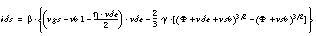
where:

Effective Channel Length and Width
The model calculates effective channel length and width from the drawn length and width as follows:


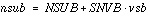
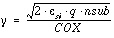
Effective Substrate Doping, nsub
Specify the model parameter SNVB to vary substrate doping concentration linearly as a function of vsb.
The  ,
,  , and xd parameters are computed using the above equation for nsub.

If SNVB is zero, then  = GAMMA. The
  value is adjusted for short-channel effect the same way as the LEVEL 2 model. Also,
  is calculated using NSUB.
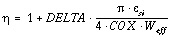
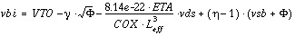
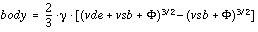
Threshold Voltage, vth
Specify ETA to include the threshold voltage reduction due to potential barrier lowering effect.
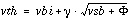
The  is modified for short-channel effect, the same as in the LEVEL 2 model, to get effective
  .
.
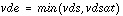
Saturation Voltage vdsat
The saturation voltage vsat is computed the same as in the LEVEL 2 model. The carrier velocity effect is included only when ECRIT is greater than zero.
ECRIT > 0,
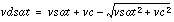
where:

ECRIT
<=
0 or MOB=7,

vsat is computed as in the LEVEL=2 model (See Saturation Voltage, vdsat).
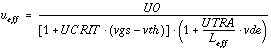
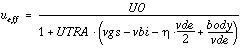
Effective Mobility, ueff
The mobility equation selector MOB controls the mobility reduction equations. In the LEVEL 8 model, set MOB to 2, 3, 6, or 7. Default=6.
MOB=2 Mobility Reduction
MOB=3 Mobility Reduction
where egfet is the silicon energy gap at the analysis temperature.
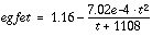
where t is the temperature in degrees Kelvin.
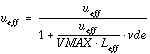
If VMAX>1,
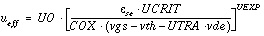
MOB=6 Mobility Reduction
For UEXP>0,
If 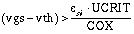
then 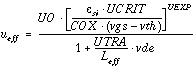
otherwise, 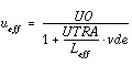
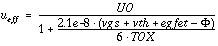
For UEXP=0
UCRIT for UEXP=0 has a dimension of (1/V).
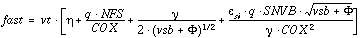
MOB=7 Mobility Reduction
where:
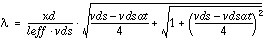
Channel Length Modulation
The equation selector CLM controls the channel length modulation equations. In the LEVEL 8 model, set CLM to 6, 7, and 8. Default=7.
CLM=6 SPICE Channel Length Modulation
If LAMBDA=0,
otherwise,

then,
NOTE: The LEVEL 2 model has no LAM1 term.
The current is modified for channel length modulation effect in entire regions as:

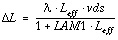
CLM=7 Intersil Channel Length Modulation
The  L is only computed for the saturation region.
vds > vdsat
and:

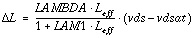
CLM=8
The  is only computed for the saturation region.
vds > vdsat
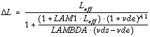
and:

Subthreshold Current Ids
The LEVEL 8 model has different subthreshold current equations, depending on the value of model parameter CAV.
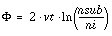
Define:
CAV 0
0
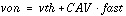
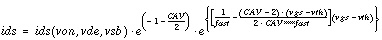
Subthreshold Region, vgs < von
If vgs>vth
If vgs<=vth
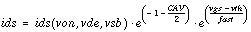
CAV=0
If CLM=8,
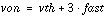
otherwise,
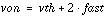
Subthreshold Region, vgs<von
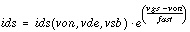
If WIC=3, the subthreshold current is calculated differently. In this case the ids current is:

N0eff and NDeff are functions of effective device width and length.
Star-Hspice Manual - Release 2001.2 - June 2001


