As a final example, analyze the behavior of the simple MOS inverter shown in MOS Inverter Circuit.
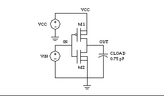
1. Type the following netlist data into a file named quickINV.sp.
M1 OUT IN VCC VCC PCH L = 1U W = 20U
M2 OUT IN 0 0 NCH L = 1U W = 20U
VIN IN 0 0 PULSE .2 4.8 2N 1N 1N 5N 20N
2. Type the following to run Star-Hspice.
hspice quickINV.sp > quickINV.lis
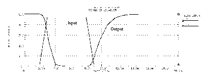
Use AvanWaves to examine the voltage waveforms at the inverter IN and OUT nodes. The waveforms are shown in Voltage at MOS Inverter Node 1 and Node 2.