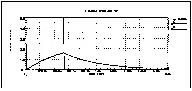


As a second example, run a transient analysis using the same RC network as in RC Network Circuit, but adding a pulse source to the DC and AC sources.
1. Type the following equivalent Star-Hspice netlist into a file named
quickTRAN.sp.
.PRINT TRAN V(1) V(2) I(R2) I(C1)
V1 1 0 10 AC 1 PULSE 0 5 10N 20N 20N 500N 2U
Note that the V1 source specification has added a pulse source. The syntax for pulse sources and other types of sources is described in Using Sources and Stimuli.
2. Type the following to run Star-Hspice.
hspice quickTRAN.sp > quickTRAN.lis
3. Use an editor to view the .
lis
and .
st0
files to examine the simulation results
and status.
4. Run AvanWaves and open the . sp file. Select the quickTRAN.tr0 file from the Results Browser window to view the waveform. Display the voltage at nodes 1 and 2 on the x-axis.
The waveforms are shown in Voltages at RC Network Circuit Node 1 and Node 2.


