This section describes the NPN and PNP BJT models.
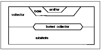
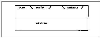
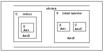
The substrate diode is connected to either the collector or the base depending on whether the transistor has a lateral or vertical geometry. Lateral geometry is implied when the model parameter SUBS=-1, and vertical geometry when SUBS=+1. The lateral transistor substrate diode is connected to the internal base and the vertical transistor substrate diode is connected to the internal collector. Vertical Transistor (SUBS = +1) and Lateral Transistor (SUBS = -1) show vertical and lateral transistor geometries.
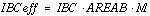
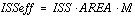
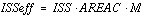
In Base, AREAB, Collector, AREAC, the views from the top demonstrate how IBE is multiplied by either base area, AREAB, or collector area, AREAC.
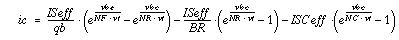
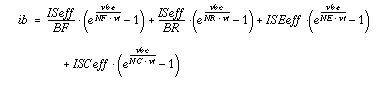
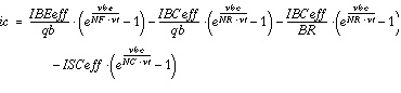
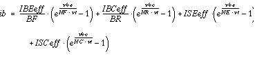
DC model equations are for the DC component of the collector current (ic) and the base current (ib).
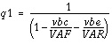
If only IS is specified, without IBE and IBC:
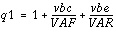
If IBE and IBC are specified, instead of IS:
The last two terms in the expression of the base current represent the components due to recombination in the base-emitter and base collector space charge regions at low injection.
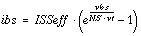
The substrate current is substrate to collector for vertical transistors and substrate to base for lateral transistors.
If both IBE and IBC are not specified:
If both IBE and IBC are specified:
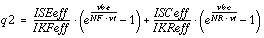
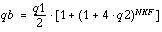
VAF and VAR are, respectively, forward and reverse early voltages. IKF and IKR determine the high-current Beta roll-off. ISE, ISC, NE, and NC determine the low-current Beta roll-off with ic.
Otherwise, if UPDATE=1 and  , then
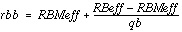
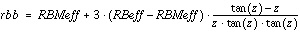
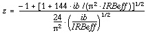
Star-Hspice provides a variable base resistance model consisting of a low-current maximum resistance set by RB and a high-current minimum resistance set by RBM. IRB is the current when the base resistance is halfway to its minimum value. If RBM is not specified, it is set to RB.
Star-Hspice Manual - Release 2001.2 - June 2001
 Vertical
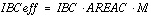 Lateral
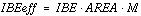 Vertical or Lateral
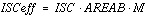 Vertical
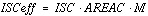 Lateral
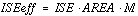 Vertical or Lateral
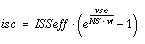


 vertical
 lateral
 , then