|
ABSH = x
|
Sets the absolute current change through voltage defined branches (voltage sources and inductors). In conjunction with DI and RELH, ABSH is used to check for current convergence. The default value equals 0.0.
|
|
ABSI = x
|
Sets the absolute branch current error tolerance in diodes, BJTs, and JFETs during DC and transient analysis. Decrease ABSI if accuracy is more important than convergence time.
If you want an analysis with currents less than 1 nanoamp, change ABSI to a value at least two orders of magnitude smaller than the minimum expected current.
The default value equals 1e-9 for KCLTEST = 0, 1e-6 for KCLTEST = 1.
|
|
ABSMOS = x
|
Current error tolerance used for MOSFET devices in both DC and transient analysis. Star-Hspice uses the ABSMOS setting to determine if the drain-to-source current solution has converged. If the difference between the last and the present iteration's drain-to-source current is less than ABSMOS, or if it is greater than ABSMOS, but the percent change is less than RELMOS, the drain-to-source current is considered converged.
Star-Hspice then checks the other accuracy tolerances and, if all indicate convergence, the circuit solution at that timepoint is considered solved, and the next timepoint solution is calculated. For low power circuits, optimization, and single transistor simulations, set ABSMOS = 1e-12. The default value equals 1e-6 (amperes).
|
|
ABSTOL = x
|
Sets the absolute error tolerance for branch currents. Decrease ABSTOL if accuracy is more important than convergence time.
|
|
ABSVDC = x
|
Sets the absolute minimum voltage for DC and transient analysis. Decrease ABSVDC if accuracy is of more concern than convergence. If voltages less than 50 microvolts are required, ABSVDC can be reduced to two orders of magnitude less than the smallest desired voltage. This ensures at least two digits of significance. Typically ABSVDC need not be changed unless the circuit is a high voltage circuit. For 1000-volt circuits, a reasonable value can be 5 to 50 millivolts. The default value equals VNTOL (VNTOL default = 50 µV).
|
|
DI = x
|
Sets the maximum iteration-to-iteration current change through voltage defined branches (voltage sources and inductors). This option is only applicable when the value of the ABSH control option is greater than 0. The default value equals 0.0.
|
|
KCLTEST
|
Activates the KCL test (Kirchhoff's Current Law) function. This test results in a longer simulation time, especially for large circuits, but provides a very accurate check of the solution. The default value equals 0.
When set to 1, Star-Hspice sets the following options:
|
|
|
-
RELMOS and ABSMOS options are set to 0 (off).
-
ABSI is set to 1e-16 A
-
RELI is set to 1e-6
To satisfy the KCL test, the following condition must be satisfied for each node:
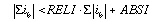
where the ibs are the node currents.
|
|
MAXAMP = x
|
Sets the maximum current through voltage defined branches (voltage sources and inductors). If the current exceeds the MAXAMP value, an error is issued. The default value equals 0.0.
|
|
RELH = x
|
Sets relative current tolerance through voltage defined branches (voltage sources and inductors). It is used to check current convergence. This option is applicable only if the value of the ABSH control option is greater than zero. The default value equals 0.05.
|
|
RELI = x
|
Sets the relative error/tolerance change from iteration to iteration to determine convergence for all currents in diode, BJT, and JFET devices. (RELMOS sets the tolerance for MOSFETs). This is the change in current from the value calculated at the previous timepoint. The default value equals 0.01 for KCLTEST = 0, 1e-6 for KCLTEST = 1.
|
|
RELMOS = x
|
Sets the relative drain-to-source current error tolerance percent from iteration to iteration to determine convergence for currents in MOSFET devices. (RELI sets the tolerance for other active devices.) This is the change in current from the value calculated at the previous timepoint. RELMOS is only considered when the current is greater than the floor value, ABSMOS. The default value equals 0.05.
|
|
RELV = x
|
Sets the relative error tolerance for voltages. When voltages or currents exceed their absolute tolerances, the RELV test is used to determine convergence. Increasing RELV increases the relative error. In general, RELV should be left at its default value. RELV controls simulator charge conservation. For voltages, RELV is the same as RELTOL. The default value equals 1e-3.
|
|
RELVDC = x
|
Sets the relative error tolerance for voltages. When voltages or currents exceed their absolute tolerances, the RELVDC test is used to determine convergence. Increasing RELVDC increases the relative error. In general, RELVDC should be left at its default value. RELVDC controls simulator charge conservation. The default value equals RELTOL (RELTOL default = 1e-3).
|
|
ITL1 = x
|
Sets the maximum DC iteration limit. Increasing this value is unlikely to improve convergence for small circuits. Values as high as 400 have resulted in convergence for certain large circuits with feedback, such as operational amplifiers and sense amplifiers. Something is usually wrong with a model if more than 100 iterations are required for convergence. Set .OPTION ACCT to obtain a listing of how many iterations are required for an operating point. The default value equals 200.
|
|
ITL2 = x
|
Sets the DC transfer curve iteration limit. Increasing the iteration limit can be effective in improving convergence only on very large circuits. The default value equals 50.
|
|
NOPIV
|
Prevents Star-Hspice from switching automatically to pivoting matrix factorization when a nodal conductance is less than PIVTOL. NOPIV inhibits pivoting. Also see PIVOT.
|
|
PIVOT = x
|
Provides different pivoting algorithm selections. These can be used effectively to reduce simulation time and achieve convergence in circuits that produce hard-to-solve matrix equations. The pivot algorithm is selected by setting PIVOT to one of the following values:
-
0: Original nonpivoting algorithm
-
1: Original pivoting algorithm
-
2: Pick largest pivot in row algorithm
-
3: Pick best in row algorithm
-
10: Fast nonpivoting algorithm, more memory required
-
11: Fast pivoting algorithm, more memory required than PIVOT values less than 11
-
12: Pick largest pivot in row algorithm, more memory required than for PIVOT values less than 12
-
13: Fast best pivot: faster, more memory required than for PIVOT values less than 13
The default value equals 10.
The fastest algorithm is PIVOT = 13, which can improve simulation time by up to ten times on very large circuits. However, the PIVOT = 13 option requires substantially more memory for the simulation. Some circuits with large conductance ratios, such as switching regulator circuits, might need pivoting. If PIVTOL = 0, Star-Hspice automatically changes from nonpivoting to a row pivot strategy upon detection of any diagonal matrix entry less than PIVTOL. This strategy provides the time and memory advantages of nonpivoting inversion, while avoiding unstable simulations and incorrect results. Use .OPTION NOPIV to prevent pivoting from being used under any circumstances.
|
|
|
For very large circuits, PIVOT = 10, 11, 12, or 13 can require excessive memory.
If Star-Hspice switches to pivoting during a simulation, the message "pivot change on the fly" is printed, followed by the node numbers causing the problem. Use .OPTION NODE to obtain a node-to-element cross reference.
SPARSE is the same as PIVOT.
|
|
PIVREF
|
Pivot reference. Used in PIVOT = 11, 12, 13 to limit the size of the matrix. The default value equals 1e+8.
|
|
PIVREL = x
|
Sets the maximum/minimum row/matrix ratio. Use only for PIVOT = 1. Large values for PIVREL can result in very long matrix pivot times. If the value is too small, however, no pivoting occurs. It is best to start with small values of PIVREL, using an adequate but not excessive value for convergence and accuracy. The default value equals 1E-20 (max = 1e-20, min = 1).
|
|
PIVTOL = x
|
Sets the absolute minimum value for which a matrix entry is accepted as a pivot. PIVTOL is used as the minimum conductance in the matrix when PIVOT = 0. The default value equals 1.0e-15.
Note: PIVTOL should always be less than GMIN or GMINDC. Values approaching 1 yield increased pivot.
|
|
SPARSE = x
|
Provides different pivoting algorithm selections. These can be used effectively to reduce simulation time and achieve convergence in circuits that produce hard-to-solve matrix equations. The pivot algorithm is selected by setting PIVOT to one of the following values:
-
0: Original nonpivoting algorithm
-
1: Original pivoting algorithm
-
2: Pick largest pivot in row algorithm
-
3: Pick best in row algorithm
-
10: Fast nonpivoting algorithm, more memory required
-
11: Fast pivoting algorithm, more memory required than PIVOT values less than 11
-
12: Pick largest pivot in row algorithm, more memory required than for PIVOT values less than 12
-
13: Fast best pivot: faster, more memory required than for PIVOT values less than 13
The default value equals 10.
The fastest algorithm is PIVOT = 13, which can improve simulation time by up to ten times on very large circuits. However, the PIVOT = 13 option requires substantially more memory for the simulation. Some circuits with large conductance ratios, such as switching regulator circuits, might need pivoting. If PIVTOL = 0, Star-Hspice automatically changes from nonpivoting to a row pivot strategy upon detection of any diagonal matrix entry less than PIVTOL. This strategy provides the time and memory advantages of nonpivoting inversion, while avoiding unstable simulations and incorrect results. Use .OPTION NOPIV to prevent pivoting from being used under any circumstances.
|
|
|
For very large circuits, PIVOT = 10, 11, 12, or 13 can require excessive memory.
If Star-Hspice switches to pivoting during a simulation, the message "pivot change on the fly" is printed, followed by the node numbers causing the problem. Use .OPTION NODE to obtain a node-to-element cross reference.
SPARSE is the same as PIVOT.
|
|
CONVERGE
|
Invokes different methods for solving nonconvergence problems:
-
CONVERGE = -1
together with DCON = -1, disables autoconvergence
-
CONVERGE = 1
uses the Damped Pseudo Transient Algorithm. If the simulation fails to converge within the amount of CPU time set by the CPTIME control option, the simulation halts.
-
CONVERGE = 2
uses a combination of DCSTEP and GMINDC ramping
-
CONVERGE = 3
invokes the source stepping method
Even if it is not set in an .OPTIONS statement, the CONVERGE option is activated in the event of a matrix floating point overflow, or a timestep too small error. The default value equals 0.
In the event of a matrix floating point overflow, Star-Hspice sets CONVERGE = 1.
|
|
CSHDC
|
The same option as CSHUNT, but is used only with option CONVERGE.
|
|
DCFOR = x
|
Used in conjunction with the DCHOLD option and the .NODESET statement to enhance the DC convergence properties of a simulation. DCFOR sets the number of iterations that are to be calculated after a circuit converges in the steady state. Since the number of iterations after convergence is usually zero, DCFOR adds iterations (and computational time) to the calculation of the DC circuit solution. DCFOR helps ensure that a circuit has actually, not falsely, converged. The default value equals 0.
|
|
DCHOLD = x
|
DCFOR and DCHOLD are used together for the initialization process of a DC analysis. They enhance the convergence properties of a DC simulation. DCFOR and DCHOLD work together with the .NODESET statement.
The DCHOLD option specifies the number of iterations a node is to be held at the voltage values specified by the .NODESET statement. The effects of DCHOLD on convergence differ according to the DCHOLD value and the number of iterations needed to obtain DC convergence. If a circuit converges in the steady state in fewer than DCHOLD iterations, the DC solution includes the values set by the .NODESET statement. However, if the circuit requires more than DCHOLD iterations to converge, the values set in the .NODESET statement are ignored and the DC solution is calculated with the .NODESET fixed source voltages open circuited. The default value equals 1.
|
|
DCON = X
|
In the case of convergence problems, Star-Hspice automatically sets DCON = 1 and the following calculations are made:
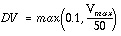 , if DV = 1000
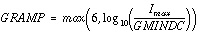
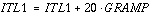
where V
max
is the maximum voltage and I
max
is the maximum current.
|
|
|
If convergence problems still exist, Star-Hspice sets DCON = 2, which is the same as the above except DV = 1e6. The above calculations are used for DCON = 1 or 2. DCON = 1 is automatically invoked if the circuit fails to converge. DCON = 2 is invoked if DCON = 1 fails.
If the circuit contains uninitialized flip-flops or discontinuous models, the simulation might be unable to converge. Setting DCON = -1 and CONVERGE = -1 disables the autoconvergence algorithm and provides a list of nonconvergent nodes and devices.
|
|
DCSTEP = x
|
Used to convert DC model and element capacitors to a conductance to enhance DC convergence properties. The value of the element capacitors are all divided by DCSTEP to obtain a DC conductance model. The default value equals 0 (seconds).
|
|
DCTRAN
|
Invokes different methods for solving nonconvergence problems:
-
CONVERGE = -1
together with DCON = -1, disables autoconvergence
-
CONVERGE = 1
uses the Damped Pseudo Transient Algorithm. If the simulation fails to converge within the amount of CPU time set by the CPTIME control option, the simulation halts.
-
CONVERGE = 2
uses a combination of DCSTEP and GMINDC ramping
-
CONVERGE = 3
invokes the source stepping method
Even if it is not set in an .OPTIONS statement, the CONVERGE option is activated in the event of a matrix floating point overflow, or a timestep too small error. The default value equals 0.
In the event of a matrix floating point overflow, Star-Hspice sets CONVERGE = 1.
DCTRAN is an alias for CONVERGE.
|
|
DV = x
|
The maximum iteration-to-iteration voltage change for all circuit nodes in both DC and transient analysis. Values of 0.5 to 5.0 can be necessary for some high-gain bipolar amplifiers to achieve a stable DC operating point. CMOS circuits frequently require a value of about 1 volt for large digital circuits. The default value equals 1000 (or 1e6 if DCON = 2).
|
|
GMAX = x
|
The conductance in parallel with the current source used for .IC and .NODESET initialization conditions circuitry. Some large bipolar circuits can require GMAX set to 1 for convergence. The default value equals 100 (mho).
|
|
GMINDC = x
|
A conductance that is placed in parallel with all pn junctions and all MOSFET nodes for DC analysis. GMINDC helps overcome DC convergence problems caused by low values of off conductance for pn junctions and MOSFET devices. GRAMP can be used to reduce GMINDC by one order of magnitude for each step. GMINDC can be set between 1e-4 and PIVTOL. The default value equals 1e-12.
Large values of GMINDC can cause unreasonable circuit response. If large values are required for convergence, a bad model or circuit is suspect. In the event of a matrix floating point overflow, if GMINDC is 1.0e-12 or less, Star-Hspice sets it to 1.0e-11.
GMINDC is manipulated by Star-Hspice in autoconverge mode.
|
|
GRAMP = x
|
Value is set by Star-Hspice during the autoconvergence procedure. GRAMP is used in conjunction with the GMINDC convergence control option to find the smallest value of GMINDC that results in DC convergence.
GRAMP specifies the conductance range over which GMINDC is to be swept during a DC operating point analysis. Star-Hspice substitutes values of GMINDC over this range and simulates at each value. It then picks the lowest value of GMINDC that resulted in the circuit converging in the steady state.
|
|
|
If GMINDC is swept between 1e-12 mhos (the default) and 1e-6 mhos, GRAMP is set to 6 (the value of the exponent difference between the default and the maximum conductance limit). In this case, GMINDC is first set to 1e-6 mhos, and the circuit is simulated. If convergence is achieved, GMINDC is next set to 1e-7 mhos, and the circuit simulated again. The sweep continues until a simulation has been performed at all values on the GRAMP ramp. If the combined conductance of GMINDC and GRAMP is greater than 1e-3 mho, a false convergence can occur. The default value equals 0.
|
|
GSHUNT
|
Conductance added from each node to ground. The default value is zero. Add a small GSHUNT to each node to possibly solve "Timestep too small" problems caused by high frequency oscillations or by numerical noise
.
|
|
ICSWEEP
|
For a parameter or temperature sweep, saves the results of the current analysis for use as the starting point in the next analysis in the sweep. When ICSWEEP = 1, the current results are used in the next analysis. When ICSWEEP = 0, the results of the current analysis are not used in the next analysis. The default value equals 1.
|
|
NEWTOL
|
Calculates one more iterations past convergence for every DC solution and timepoint circuit solution calculated. When NEWTOL is not set, once convergence is determined, the convergence routine is ended and the next program step begun. The default value equals 0.
|
|
OFF
|
Initializes the terminal voltages of all active devices to zero if they are not initialized to other values. For example, if the drain and source nodes of a transistor are not both initialized using .NODESET or .IC statements or by connecting them to sources, then the OFF option initializes all of the nodes of the transistor to zero. The OFF option is checked before element IC parameters, so if an element IC parameter assignment exists for a particular node, the node is initialized to the element IC parameter value even if it was previously set to zero by the OFF option. (The element parameter OFF can be used to initialize the terminal voltages to zero for particular active devices).
The OFF option is used to help find exact DC operating point solutions for large circuits.
|
|
RESMIN = x
|
Specifies the minimum resistance value for all resistors, including parasitic and inductive resistances. The default value equals 1e-5 (ohm). Range: 1e-15 to 10 ohm.
|
|
CSCAL
|
Sets the capacitance scale. Capacitances are multiplied by CSCAL. The default value equals 1e+12 (thus, by default, all capacitances are entered in units of pF).
|
|
FMAX
|
Sets the limit for maximum pole and zero angular frequency value. The default value equals 1.0e+12 rad/sec.
|
|
FSCAL
|
Sets the frequency scale. Frequency is multiplied by FSCAL. The default value equals 1e-9 (thus, by default, all frequencies are entered in units of GHz).
|
|
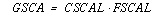
GSCAL
|
Sets the conductance scale. Conductances are multiplied by GSCAL. Resistances are divided by GSCAL. The default value equals 1e+3 (thus, by default, all resistances are entered in units of k ).
).
|
|
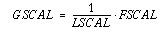
LSCAL
|
Sets inductance scale. Inductances are multiplied by LSCAL. The default value equals 1e+6 (thus, by default, all inductances are entered in units of µH).
The scale factors must satisfy the following relations:
If scale factors are changed, it might be necessary to modify the initial Muller points (X0R, X0I), (X1R, X1I) and (X2R, X2I), even though Star-Hspice multiplies initial values by (1e-9/GSCAL).
|
|
PZABS
|
Sets absolute tolerances for poles and zeros. This option affects the low frequency poles or zeros. It is used as follows:
If 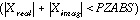 ,
,
then  and
and  .
.
It is also used for convergence tests. The default value equals 1e-2.
|
|
PZTOL
|
Sets the relative error tolerance for poles or zeros. The default value equals 1.0e-6.
|
|
RITOL
|
Sets the minimum ratio value for (real/imaginary) or (imaginary/real) parts of the poles or zeros. RITOL is used as follows:
If 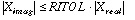 , then
If  , then
The default value equals 1.0e-6.
|
|
(X0R,X0I),
(X1R,X1I),
(X2R,X2I)
|
The three complex starting points in the Muller pole/zero analysis algorithm are:
X0R = -1.23456e6 X0I = 0.0
X1R = -1.23456e5 X1I = 0.0
X2R = +.23456e6 X2I = 0.0
These initial points are multiplied by FSCAL.
|


